|
Professional design GFF (gain flattening filter) with excellent optical path design make flatness and noise reach the best optimization. It can provide 40~80 channels, and above 35nm flatness.
The optical circuit is designed especially for digital optical fiber communication system including(1) lower noise figure(2)high output booster and high sensitivity Pre-Amplifier improve the system loss budget(3)Broad input power range and output power adjustable make it use easily. .
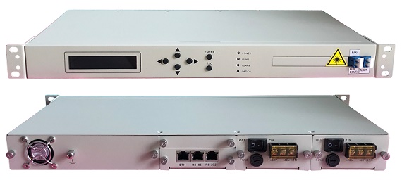
The design of dual Power Mixed and hot swap make it has longer MTBF. Also, the power system can be backup.
Employ the intelligent temperature control system,the fan is on when the module temperature over 45℃, meanwhile it will stop as the temperature is under 40℃, which makes sure the thermal stability and fan’s long life-time, meanwhile, the professional air flow design can also ensure the best temperature stability.
Intelligent network management system. Perfectly network interface: Ethernet, RS-485 and RS-232 network interface,and the open mib ensure the connectivity with all other network management system.
Feature
●Low noise figure: Typical 4.5dB
●High Flatness: Typical 1dB
●Redundancy hot swap power module: mixed plug 110/220VAC and -48VDC
●Cover whole C+L band: Carrier 40 or 80 chs
●apply to Long haul transmission system cover dispersion
●Perfect network management interface:Ethernet,RS-485 and RS-232.
●Support Telnet and SNMP network management
●Gain can be adjustable by network and manual
●High precise AGC and ATC circuit
●High saturation output power
●OEM is available
●Compatible with Bellcore GR-1312-CORE
Application
DWDM Inter-stage Transmission system
Block diagram
Optical Characteristics
|
Parameter |
Symbol |
Min |
Typ |
Max |
Unit |
|
Wavelength |
λc |
1529 |
1550 |
1564 |
nm |
|
Saturation output power(1) |
Po |
------ |
------ |
20 |
dBm |
|
Input power |
Pi |
-35 |
------ |
+6 |
dBm |
|
Gain Flatness |
GF |
------ |
1.0 |
------ |
dB |
|
Inter-stage insertion loss |
Lm |
------ |
------ |
15 |
dB |
|
Gain |
G |
------ |
20 |
33 |
dB |
|
Noise Figure(2) |
NF |
------ |
4.5 |
----- |
dB |
|
Output Power Stability |
ΔPo |
----- |
±0.05 |
±0.1 |
dB |
|
Return Loss |
RL |
------- |
------- |
-45 |
dB |
|
PDG |
PDG |
------ |
------- |
0.3 |
dB |
|
PMD |
PMD |
------ |
------- |
0.5 |
ps |
(1):Optional(2):Test at 0dBm input.
Electrical Characteristics
|
Parameter |
Symbol |
Min |
Typ |
Max |
Unit |
|
Power Supply ※ |
Vps |
85/170 |
110/220 |
132/264 |
VAC |
|
Consumption ※※ |
P |
----- |
----- |
18 |
W |
※110VAC,220VAC and -48VDC is optional.
※※Actual consumption depends on the output power and environment temperature.
Environmental Characteristics
|
Parameter |
Symbol |
Min |
Typ |
Max |
Unit |
|
Operating Temperature |
Tw |
-5 |
----- |
60 |
℃ |
|
Storage Temperature |
Ts |
-40 |
----- |
80 |
℃ |
|
Humidity(3) |
------ |
10 |
------ |
85 |
% |
(3):Non-Condensing
Order Information
OPA-1550D A-B-C-D-E-F-G
|
A |
B |
C |
D |
E |
F |
G |
|
Application |
Input power |
Output power |
PS1 |
PS2 |
Fiber connector |
NM |
|
DWDM inter-stage |
5: -3~+10dBm |
10: 10dBm |
1:110VAC |
1:110VAC |
1:SC/UPC |
0:None |
|
9: others |
20: 20dBm |
2:220VAC |
2:220VAC |
2:SC/APC |
1:SNMP |
|
9:others |
3:110~220V |
3:110~220V |
3:FC/UPC |
|
|
|
4:-48VDC |
4:-48VDC |
4:FC/APC |
|
|
|
9: others |
0:None |
5:LC/UPC |
|
|
|
|
|
6:LC/APC |
|
|
|
|
|
|
9:others |
| |